Friday, October 11, 2013

Canopy Installation, Part 4

Another cool idea that Van's came up with for the RV-12 is a nice, lightweight glareshield.  A bubble canopy and a complete glass panel on a sunny day can be a recipe for visibility issues of the instrumentation.  After seeing one installed on VAF.net, I had to have one.  I ordered it and was not disappointed.  As an added bonus, it appears to be finished in the exact same Sherwin Williams JetFlex Blue Black color of my interior.....so much so that I am not going to touch the nice exterior finish.  I did apply 3 coats of a nice flat black on the unfinished interior side of the glareshield.  I used Rustoleum's Painter's Touch 2X paint + primer rattle can, which is advertised as "also bonds to plastic!".  I was able to get a nice finish with that paint.  As I will document later, I also used it on the inside of the plexiglass canopy...but more about that at the proper time.  The photos below show the nice form and fit of the glareshield along the front canopy bow.


The glareshield will be fastened with the front canopy bow's #6 countersunk screws, washers and nuts, which will also be holding the canopy in place.  I opted to NOT use rivets.


 Next up on the canopy install was the manufacture and installation of the canopy guide blocks.  In another post on VAF, an RV-12 builder remarked that he had shaped (rounded corners, edges) his guide blocks with his router.  As it sounded like a good idea, I broke out my home brewed router table rig and set about to finish-shaping my guide blocks.

Scary tool that router with its bit turning at the "speed of heat" about 1/4 inch from one's digits!


In the end, I finished with all digits still attached and two nicely shaped canopy guide blocks.


Below is clearer picture of my rig with the set up I used to do the job.


The guide blocks were used to guide a tap to thread the holes that were drilled into the roll bar.  After tapping the holes and then cleaning up, the guide blocks were fastened to the roll bar.


I will have to plead ignorance at this point and say that I don't remember if I have previously mentioned my use of the Viking Shield.  The shield is simply a pre-made gelcoated, fiberglass trim piece that Viking Aircraft Engines sells to alleviate the RV-12 builder of that task beginning on page 34-14 of the builder's manual.  I opted to purchase one.

To be honest, I was disappointed with the lack of rigidity of the trim piece as it probably has only 2 layers of glass plus the gelcoat.  I was impressed with the pristine gelcoat finish which would completely eliminate any finish work getting the fiberglass part to the paint -ready stage.

I was determined to give this piece a fair shake (as opposed to just doing the prescribed manual layup) so my first order of business was to attempt to bring it up to my standards of at least 4 layers of glass.  Pictured below are a few shots of the supplemental glassing process.  I will confess to the fact that I simply used some cheap polyester resin and some 6 ounce glass cloth purchased from the local auto repair shop.  I did squeegee as much of the excess resin from the lay up as possible to keep it light.  The final trimmed piece of which I don't yet have a picture turned out nice.  The modified fairing's rigidity is now what I wanted it to be.


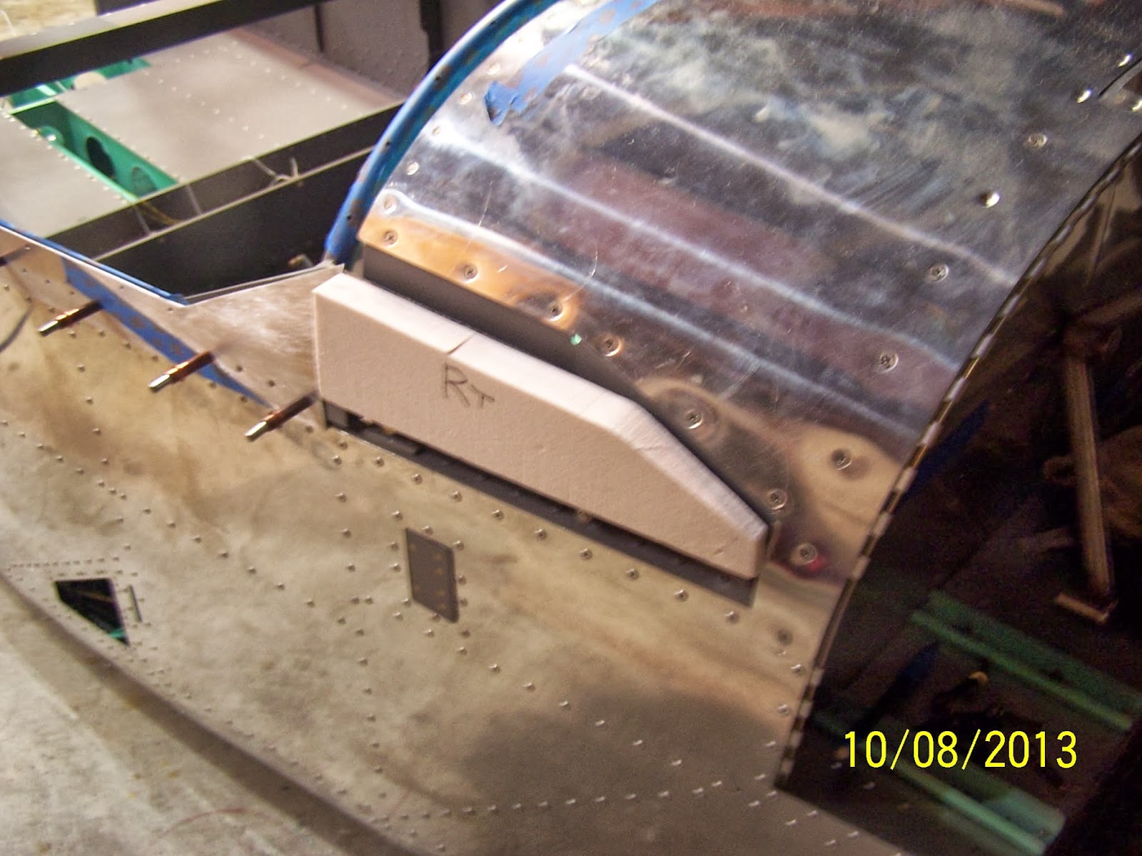
The next step in the process involved the trimming of the two blocks of canopy foam....and the subsequent bonding to the forward canopy frame.  Below is a picture of the trimmed foam block, nearly ready for bonding to the canopy frame.


Checking for fit of the foam block on the canopy frame - looks acceptable.


For bonding the canopy foam to the frame, I opted to use an epoxy resin in lieu of the low-tech polyester resin.  The Gflex epoxy resin is a West System product that I purchased at our local West Marine store.  Next to it is the 1 pound bag of flox (chopped cotton fibers) purchased from Aircraft Spruce.  The epoxy resin mixes at a 1:1 ratio, and the digital scale makes it a no-brainer of a process.  The builder's manual states to add enough flox "until the mixture is just thick enough that it won't pour when the mixing cup is tipped."  Armed with that info, I added small increments of flox to the resin mixture until it seemed to be thick enough....like a thin paste.


 After the canopy foam blocks were coated with the epoxy/flox mixture, it was time to let the duct tape do its thing and hold in place until the next day.  Next up will be the sanding/contouring of the foam.


Sunday, September 22, 2013

Canopy Installation, Part 3

Part 2 of the canopy installation installment ended with my unsuccessful attempt to repair a hairline crack in the forward cross tube of the canopy frame.  After I broke that externally sleeved repair, I planned on implementing an internal solid rod sleeve.  I had the common sense to also order some tubing as well that could also serve as an internal sleeve...and that is what I ended up going with as shown below.  The first picture shows the 4.5 inch internal sleeve drilled and cleco'd half way in place.  I did use countersunk blind rivets as shown in the next photo.


A final shot of the repaired butt weld area that is no longer welded!  I would add that the forward canopy bow now fits perfectly with respect to the instrument panel and provides the prescribed clearances.


Forward canopy bow with correct clearance from instrument panel.


View looking aft of the forward canopy bow.


Once the debacle of the broken butt weld was behind me, it was a quick matter to proceed with the fitting of the canopy to the frame and fuselage.  The first few photos below show the canopy laying in place prior to duct taping into final position, holding the lengthwise and lateral dimensions as called forth in the plans.

 
Now visible is the blue painter's tape running along the forward and aft canopy frames.  The forward bow will be marked for drilling by pressing the tape onto the bow by pushing on the canopy so as to leave an impression.


Next, the canopy was secured with duct tape into final position with the aforementioned measurements in place.


I was not satisfied with the impressions left on the forward canopy bow with the blue painter's tape so I ended up switching to traditional masking tape and was much happier with the results.  Below, I am drilling the #40 holes in the canopy bow at the prescribed 2-inch intervals.
 
 
After pre-drilling the forward canopy bow, it was time to re-install the canopy and drill the plexiglass. Shown below is a shot of the drilling of the rear canopy bow.


And finally, the canopy gets to perform its porcupine impression with a myriad of clecos.


Next up were the canopy skirts, which get dimensionally positioned along the length of the canopy with some duct tape and then the drilling and cleco'ing process resumes.


Wednesday, September 18, 2013

Canopy Installation (and a Set Back), Part 2

Before continuing with the installation of  the canopy attach angles and other subassemblies, it was time to prime and top coat the canopy frame.  Below is a shot of the finished product.  Note the forward tube is only top coated at the ends where it might be partially exposed.  I plan on installing the glare shield which should hide the underside of the cross tube.  The top side of the cross tube should be hidden by the fiberglass fairing.


The next steps involved fluting, drilling, deburring, match hole drilling and final installation of the forward and aft canopy attach angles.


Next, the canopy frame was fitted to the fuselage with the obligatory 1/8 inch cardboard padding between the canopy frame and the fuselage, shown below taped into place.


As I was measuring for the 7/16 inch clearance between the forward surface of the canopy frame and the instrument panel, I found that I did not have sufficient clearance.  After some bending, I finally arrived at this conclusion below:


Not a very good picture, but there is a hairline crack in the butt weld!  After speaking with Vans builder support, they suggested an external sleeve which I implemented as shown below, with 2 tubing halves, each with 2 rivets, and further bonded with ProSeal.


Now I found that I had even less clearance with the .035 inch thick external sleeves.  In short, the canopy frame would again NOT clear the instrument panel!  Back to the aggressive bending to make this thing fit....which led me to this new conclusion:


When the weld broke completely through, I removed my external sleeves and to my surprise found the factory's internal sleeve had taken a permanent set from my vigorous bending.


 The next step will involve another internal sleeve, made of rod stock and 4 threaded and countersunk machine screws.  Hopefully that arrangement will survive the additional bending that is going to be required to get the canopy frame to have sufficient clearance with the instrument panel!  The saga continues.

Saturday, August 31, 2013

Flight Controls, Part 3

After finishing the painting of the flap handle and the completion of the wiring harness, it was time to continue the flight controls installation.  First order of business was to install the rod end bearing into the flap handle's pushrod and then connect it to the flap handle.


 Prior to the flap installation, the brake reservoir was installed and then a tee was threaded into the unit followed by the remaining 2 brake lines installed into the tee as shown below in the following 2 pictures.


Next, the flap handle blocks and the flap handle assembly was installed between the seat ribs, on the centerline.


The flap handle pushrod and flaperon mixer were bolted to the flaperon mixer arms as shown below.


The control stick pushrods are now installed from the base of the control sticks to the forward end of the flaperon mixer as shown below.


The flaperon pushrods are attached to the aft end of the flaperon mixer.


Another shot of the flaperon pushrods and their forward attach points.


The aft end of the flaperon pushrods are attached to the flaperon torque tubes, which are hinged onto the bearing brackets.


 Next, the flap detent bracket is riveted to the plate and angles in preparation for the fitment of the flap fork assembly inside of the flap handle assembly.


 The flap detent bracket assembly is slid through the flap handle with the internal flap fork assembly, which includes the compression spring.  The detent assembly is screwed into place with shims, which will simulate the cover plate.  During this process, the length of the internal fork assembly is verified to insure that the flap knob (button) does not extend too far beyond the length of the flap handle.  I installed 2 other springs (less stiffness) after builder complaints of the stiffness of the original.  In the end, I chose the original, stiffer spring for my flap handle assembly.  When the flap moves from one position and locks into the next, it sounds like a rifle shot!  Quite a reassurance that the flap handle is locked into its position.