Thursday, February 25, 2016

Wing Tank and Skins - Final Installation


Finally after all of the hullabaloo associated with the wing tanks and their plumbing...and testing, it was time to wrap it all up.

The following shots are of the right wing's root bay with the vent and fuel lines installed and hooked up.  The skin is lifted up to reveal the plumbing.


The next picture shows the fuselage vent line termination as it runs aft to the belly vent.  This picture is of the passenger side.  You can also see the protruding standpipe.  Note the gray colored support bracket that was associated with the previous fuselage vent plumbing.  It was removed as it was not needed in the modified (and final) version of the fuselage vent system.


A final view of the vent and fuel line plumbing of the right wing, fully seated, prior to skinning the wing.


One final picture, showing a late modification, namely the olive drab colored tube near the bottom.  There was a slight tendency for the fuel line to lift when the excess fuel line was retracted into the root wing bay as the wing was seated against the fuselage.  This simple tube was installed between the ribs to retain the slight downward slope of the fuel line upon final installation of the wing to the fuselage.


One last picture, I promise, of the right wing and its plumbing.  Seen here are the quick disconnect fittings and the clearance available to accomplish removal/installation.  Quite happy with the way it came out.


As the wing skinning process began, service bulletin 14-11-03, was accomplished, as denoted below.


Yours truly popping one of a few rivets in the lower wing skin.


One section at a time with lots of cleco's to remove any twist/distortion to the skins so the matched holes align perfectly.  Lots of fun.


Family affair...here the older son home from grad school over Christmas break renews acquaintances with N79AM.


More family times with son #2 home from Aggieland over Christmas break...the brain trust hard at work.


The access panel adjacent to the wing tip, in the last wing bay.  Ease of access to all fittings of the wing tanks and interconnect plumbing near the filler neck.


Time to flip it over and work the top skins....


An almost finished product.  Wing tip comes next.


 The wing tip going into place.


A good shot of the wing tip access panel showing ease of service of any fitting associated with the wing tank filler neck.


The left wing has the pitot tube, angle of attack plumbing and the stall warner assembly.  Below is a shot of the externals mounted on the underside leading edge of the wing.


And next, a shot of the internals.  Pitot mast on the left with the clear tubing (transitioning to the green tubing), then the dab of high strength silicone attaching the green tubing to the angle of attack probe (an oversize blind rivet with shank removed) and finally, the stall warner attached to the rib on the right....all flanked by the wing access panel.


Next big milestone was the fitting of the wings to the fuselage.  Shown below are shots of the right wing going into the fuselage for the first time.  A couple of trim cuts to remove slight interference and we were home free.  No big deal fitting one wing at a time...it became a big deal when both were going in together though.


Not a great picture for all the drama required to get the left wing to seat properly.  I had to resort to some ratcheting straps to get sufficient compression on the wing to fit into the bushings.  Also used a Harbor Freight muffler expansion tool to aid in the process.  In the end, with sufficient silicone grease, the spar pins went quite nicely into the bushings.


Use a ratcheting strap from the roll bar to the wing tip and another from the wing tie down ring to the landing gear leg and start the balanced ratcheting.  When you're close, just apply a little pressure from the muffler expansion tool to the spar pin bushing, remove it, add a bit of grease and insert the spar pins - good to go!  Took about an hour.


The end result - first wing fitting!  A site for sore eyes.


What could be better than a "blessing of the fleet" from  your loved ones?  I'll carry these notes (on the interior wing skins) of well wishes with me wherever I fly.


Wednesday, February 24, 2016

Wing Tank Vent System Changed!

If you've been following along with the wing tank installation series, be forewarned that the previously documented fuselage portion of the wing tank vent system has been changed significantly. There was something that was unsettling me about the complexity of the vent system that I could not readily identify.  The plumbing just had to be simplified.  My RV-12 building buddy near Austin, Texas had the trick.

He had located the belly vents aft of the baggage bulkhead, which had the tremendous benefit of eliminating one of the two interconnect vent lines.  Once I saw it, I was all in.  It was such a simple upgrade!  Thanks Dick.

 Below is a reasonable overview of the fuselage vent system.  Of particular note are the partial sheets of aluminum jigged into place where the tailcone will eventually be attached to the forward fuselage.  This jigging was set up to locate the external mounting of the belly vents and siphon break exit.  A similar jig is seen in the upper right portion of the photo which details the location of the siphon break.


This is a close up from the side at tailcone floor level of the vent line as it exits the fuselage.


 Next, is a close up view of the cross over vent line which connects the two vents to one another.


The siphon break line exits through an aluminum bung with an AN fitting....again, through the top of the tailcone.  This shot just shows the tailcone on the floor of the shop.


Shown below is a poor quality picture of the screen covering the opening of the siphon break line on the tailcone.


Next is a shot of one of the externally mounted belly vents on the tailcone.


Once the tailcone was mounted, the plumbing associated with the belly vents and siphon break was secured to the skin of the tailcone.  Shown below is the passenger side belly vent plumbing.


 Also on the passenger side is the plumbing associated with the siphon break.


 That should about do it for the final configuration of the fuselage vent system....and I am quite pleased with it.

Thursday, October 15, 2015

Wing Tank Leak and Flow Check


Update:  The flow tests documented below with color photographs were performed in October 2015, as noted by the timestamps on those pictures.  Since that time, I have redesigned the fuselage portion of the wing tank vent system.  All of the changes associated with the redesigned vent system necessitated another set of flow tests which were not documented with photography.  Additionally, these original tests produced overly optimistic flow rates due to a siphon effect which was unknowingly created by draping the exiting fuel line over the edge of the test bench.

The most recent flow tests (performed in December 2015 and January 2016) performed with the modified vent system eliminated the error created by the siphon and yielded an accurate picture of the fuel system's flow performance.  These latter tests were performed by timing the accumulated weight of fuel, in one pound increments, as it drained from the fuselage standpipe (think of it as a header tank) after the wing was fueled.

The screen capture below is a final flow test of the left wing featuring about 32 pounds of gasoline, configured as it will be installed on the fuselage for conventional flight.  As you can see, the flow rates ranged from a high of 7.66 gallons per hour down to 6.89 gph...and this is the last 5+ gallons of gas in a 10 gallon wing tank.  Of course since the wing is statically tested, there is no favorable pressure gradient from the belly vents to assist the gravity flow.  Even so a nominal 7 gph per wing  (14 gph for the system) should yield a very respectable flow to an engine that really cannot consume more than about 7 gph at redline.  A second screen capture (below this one) shows the same flow test with the conventional vent system and the fuel cap removed for additional venting.  An increase in flow rate of about 10% resulted from this other test.


Here is the second test with the modified (fuel cap removed from wing tank) vent system.  It shows about a 10% increase in flow rates.


That's about it for the documentation on the final wing tank installation that I will be flying with.

=========================================================================

PLEASE IGNORE THE FOLLOWING PICTURES AND TEXT AS THEY WERE AN INTERMEDIATE RESULT AND DO NOT REFLECT THE FINAL CONFIGURATION  OF THE FUEL SYSTEM.

=========================================================================

Now that the fuel and vent plumbing in the wing itself is complete, it is time to fill her up and see what happens.

First thing needed is to jig up the wing into it relative position as when mounted on the fuselage.  I created a wing tip support jig at the second from the end rib.  This jig supported the wing beneath the main spar and aft, toward the midpoint of the remaining portion of the rib, right at the rear, smaller wing tank.


The wing tip jig was made as a result of some measurements at the root end of the wing.  I placed the spar pins in their respective holes and laid a level across to find the dihedral angle.  At that point, I was then able to create the wing tip jig as shown in the first picture.  Below is the spirit level laying across the spar spins.  In the left side of the picture is the vent line reaching upward.


I would say that's pretty close to level so the dihedral angle is set.


Another view of the wing showing the drain line and a gas tank at the root end.


Close up of the fuel line running to terminate in the drain tank on the floor.


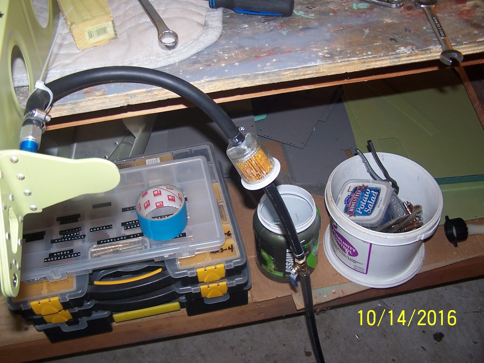
 In the shot below, you can just see the valve downstream of the fuel filter.  I ended up reversing their order in subsequent tests and for some reason, the tank seemed to flow better.


Gas flowing...


...and flowing.


Overall, I'm pretty pleased with the results.  There were no leaks that I could find.  Flow, although not measured, seemed pretty good.  One thing that worries me is that after the fuel drained to a stop, I still had about 1 gallon of gas that remained in the tank....not sure what to think about that.

On another positive note, the tank took all but about 15-20 ounces of 10 gallons!  Counting the stand pipe int he fuselage, this will be an honest 20 gallon capacity fuel system.