The wing tank vent system actually begins at the filler neck of each wing tip. Both tanks in each wing terminate at the filler neck. From a point just below the filler neck's fuel cap, an elbow connects to 1/4" aluminum tubing which runs back to the wing root where it ties into the vent line in the fuselage.
Before the vent line returns to the wing root though, it also picks up the interconnecting vent line between the tanks as shown below.
Next shot below shows the ventl ine running from tip to root.
At the root the line terminates into a bulkhead elbow in the second rib.
Another jog and another bulkhead elbow and the line terminates, awaiting a connection with a quick disconnect valve some fuel line and its connection with the fuselage vent.
The fuselage vent system begins at the fuel standpipe (like a header tank and mounted in the forward corner of the baggage compartment) and terminates with the fuselage belly vents. The top bung with the tee sends one vent line to the belly vents and the other side runs to the interconnect between the left and right wing tanks.
The picture below shows the upper run of the fuselage vent line heading through the baggage bulkhead.
The view from the standpipe looking aft.
This bulkhead elbow on the backside of the baggage bulkhead sends this component of the fuselage vent system upward to the top of the fuselage.
This picture will give you a better idea of the routing to the top of the fuselage.
The tee fitting in the lower portion of the photo above is emerging from the passenger side belly vent. Both belly vents are shown below in the next picture.
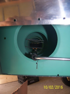
The picture below shows the pilot side belly vent from inside the fuselage as its line runs aft toward the baggage bulkhead.
Here is a side view of the pilot side belly vent plumbing. Shown at the bottom is the fuselage interconnect vent line, which will be detailed later in this post.
Throughout the vent line routing, I have taken precautions to support the thin aluminum tubing with fuel line and safety wire as shown below. A small 1/16" hole provides the attach point to the structure.
The shot below details the vent line connection between the two fuselage belly vents. This line will be anchored to the tailcone floor in a manner similar to that shown above.
Another vantage point from the passenger side to pilot side.
If you're still following along, that concludes the one side of the fuselage vent system.
Now, back to the standpipe for a brief narrative of the other component of the fuselage vent system - the interconnect system. We now follow the vent line downward from the tee fitting on the upper end of the standpipe.
Shown below is the vent line emerging from below the baggage compartment floor and into another tee fitting. One leg of the tee runs to the elbow bulkhead fitting that protrudes from the passenger side of the fuselage. The other leg of the tee fitting sends the interconnect line across the fuselage to a similar elbow bulkhead fitting on the pilot side of the fuselage.
You can see the sheathed vent line running across the fuselage from here. Note the control cables for the stabilator and rudder laying slightly above the vent line.
The photo below shows the termination of the pilot side of the interconnect.
Last two pictures illustrate the pilot side interconnect terminating on the fuselage skin.


No comments:
Post a Comment