Saturday, September 29, 2012

Mid-Fuselage Parts Assembly, Part 1

After what has seemed like an eternity, the entire part count of the mid-fuselage section has been prep'ed: cutting, deburring, dimpling, drilling and finally PreKoting, priming and the top coat.  Now the payback for all of the preparations - getting to assemble the sub-structure.

The first step is to attach the baggage floor to the aft side of the center section which is immediately followed by the baggage floor ribs.  Below is the process of cleco'ing the ribs to the baggage floors.  In this image the structure is inverted and your view is from the inside.


 The next view is of the entire center section and baggage ribs and floor.


Detail of the attachment of the ribs to the center section web.


Overall view of the center section with the baggage section attached.


Another angle...


The aft bulkhead of the baggage section contains "pockets" or receptacle supports at each end where the rear wing spar assemblies are supported by the fuselage.  Below is a detail shot of the receptacle support cover plate.  The actual support fitting is not shown as it is beneath the riveted plate.


Riveting the rear spar receptacle support and cover plate on the aft baggage bulkhead...on my step stool, about 7 feet in the air.  My work bench is pretty tall!


Next comes the seat ribs and the accompanying seat belt attachments.  There are 8 ribs in total which are assembled into right seat and left seat assemblies.


Shown below is one half of the left seat assembly which also contains a pulley bracket sub-assembly, shown in detail in the previous blog post on mid-fuselage parts preparation.


Another view of the left seat assembly.


Below, both of the seat sub-assemblies are shown.  Notice the darker colored doubler on the middle rib of the left seat assembly (shown on the right side of the picture).  That doubler is for the auto pilot servo if I decide to install it.  Unfortunately, I missed priming this part with the Deft primer, so I cheated and prepped the part with Scotchbrite in a warm solution of dish soap followed by final cleaning with acetone and 3 light coats of Duplicolor self-etching primer.


A final portrait of the seat rib assemblies less the 4th rib in each prior to installing with the respective seat bottom skins.


Thursday, September 13, 2012

Mid-Fuselage Parts Preparation (Center Section, Ribs & Skins)

Parts preparation begins for the fuselage - specifically the mid-fuselage, which incorporates many sub-assemblies and most notably the Center Section.  The Center Section is the central structural assembly which "holds" the main spar of the wing and serves as the attach point of the main landing gear.

But this installment is about parts preparation, so onward with the pictures.  After the hole and edge deburring, the parts were PreKoted as usual with ScotchBrite pads.  The following image shows seat, baggage and step area floor skins as well as a bulkhead.  There are a few other smaller parts shown as well.  Most, but not all of these are primed on only 1 side as the other side is going to be seen on the inside of the cockpit.


For these interior parts a primer coat and a final topcoat will be applied.  The requirement is for the topcoat to be applied within 2-4 hours of the primer's application to insure a good chemical bond between the two.  Since I am currently out of primer, this process must be deferred until I have everything in stock.  I just today received the first quart of the topcoat product.

I have decided to use a Sherwin Williams Aerospace paint called JetFlex WR for the topcoat.  In particular, I have chosen Blue Black, which looks like a dark gray color with a flattening agent added to hopefully minimize the possibility of interior glare on the bubble canopy.  The JetFlex WR product is water reducible.  With my emphasis on chromate-free products, and the appeal of water as a thinning agent, its choice was almost a no-brainer.  Furthermore, many builders on the Vansairforce.net website speak highly of its ease of application, hard finish and pleasant appearance. To further seal the deal, JetFlex WR is a one part product - just open the can, stir, pour into the gun and shoot.

Next are the seat, baggage and step ribs.  Notably absent from either of these two pictures is the large bottom skin, which has also been primered.  At over 6 feet long and 4 feet wide, it ha been stored in the garage, I mean hangar, rafters.  Also missing from the pictures is the Center Section itself.  I have some machine work to perform before it is ready to be prep'ed for primer and top coat.


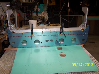
Next day, I brought the floor skin out of storage to jig both the aft bulkhead and the factory-manufactured Center Section.  Clamps shown below secure the bulkhead to the Center Section, which is cleco'd to the floor.  This sets the lateral vertical position of the bulkhead on the Center Section.  Next is the match drilling of #30 holes in two rows along the top edge.  This would be a view from the firewall looking aft.


And another view from what would be the baggage compartment looking forward.


An orthogonal view showing the entire arrangement.


After securing the aft bulkhead by drilling about half of the 70-something holes, the Center Section was removed from the floor skin for easier orientation in drilling the remaining holes.


Shown below is the assembled flaperon/mixer arm assembly which is ready to install.


Next is the assembled pulley bracket.


Completed bearing bracket assemblies.


 Finally....the first parts with final interior color - JetFlex WR Blue Black!
 
 
The last of the mid-fuselage parts receiving their primer inside the paint booth. After these parts receive their top coat of the JetFlex, it will be time to get to assembling the mid-fuselage.


Monday, September 3, 2012

Empennage & Tailcone Fit Up

With all major subassemblies completed, it was time to fit up all of the empennage to the tail cone.  The basic intent is to ensure full range of motion of the tail surfaces without any binding, chafing or otherwise unintended contact.  First picture below shows the fin (less the leading edge cuff installed) and rudder installed.


From the other direction...


Next view with the stabilator and anti-servo tab with the electric trim servo installed as well. 


After installation of the empennage, it was observed that the stabilator/AST/trim motor assembly and rudder travel in all directions was free and clear.  Onward and upward!