The fuel system work began with a deviation from the plans. Because N79AM will be Viking powered, a Honda Fit automobile conversion, the normally installed Facet fuel pump was replaced with a drain valve beneath the baggage compartment floor. The Rotax 912S-based RV-12 does not feature a fuel tank drain other than the gascolator (if you consider that a drain) at the firewall. The Viking powered RV-12 utilizes two high pressure fuel pumps (a primary and backup), mounted in the forward console, where the FT-60 (a.k.a. the red cube) fuel flow transducer resides. The photo below shows the original fuel pump mounting bracket, but with an AN tee fitting that will serve as the mainstay of the drain valve. Also shown are a spacer plate and a lock plate that will hopefully keep the bushing (threaded into the vertical leg of the tee) from turning if I ever decide to remove the drain valve for a more rapid fuel tank dump. On the right side is the drain valve and washers for mounting. Locktite 567 is the thread sealer/lubricant for sealing the threads.

View of the underside of the drain valve assembly with the lock plate in place and the spacer plate along side.
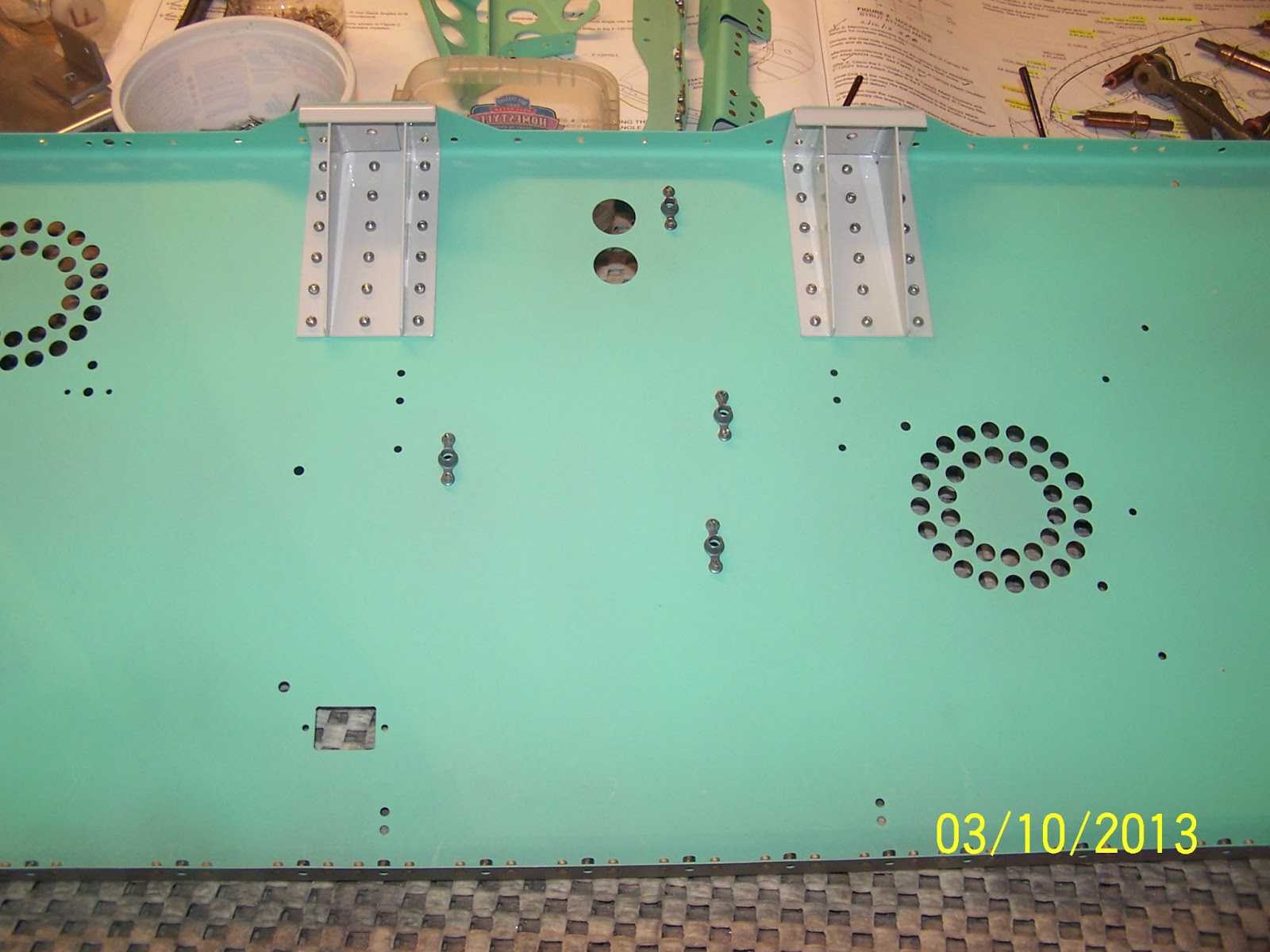
Top view of the drain valve installed in the original location of the Facet fuel pump in a standard RV-12.
Here is a poor photo of the exterior of the bottom skin, where the drain valve will protrude from the aircraft.
Next, the fuel line construction (bending) began in earnest. Shown here is the tubing bender in action. Prior to the bending is the flaring process (not shown).
After a few bends, you end up with a nice run of line that, in this instance, is to extend from the bottom of the fuel tank to the fuel drain valve. Don't flare the end of the tubing until you put the sleeve and nut in place. Don't ask me why!
And here is a close up of this section of fuel line installed in the aft section of the fuselage. In the upper right is the attach point to the fuel tank.
The next run of fuel line is to traverse from the outlet of the fuel drain valve upstream all the way to the fuel shutoff valve, located in the center compartment beneath the two seats. In this photo, we see the dog-leg that is required to route the line from the outlet of the valve up to and through a couple of bulkheads. This run is nearly 41 inches long and features a couple of difficult bends. The first bend (downward) is required to prevent possible interference with the flaperon mixer. A final jog upward in the fuel line is required to properly mate the terminus of the fuel line with the shutoff valve.
Following is a picture looking aft from the mounted fuel shut off valve to the drain valve.
Close up of the fuel shut off valve, before it was mounted in its designated location.
Another angle showing the lengthy run from just forward of the drain valve to the fuel shut off valve.
Next job was to install 2 low pressure fuel filters (100 micron) upstream from the fuel shut off valve. These redundant fuel lines will connect to the 2 fuel pumps spec'ed by Viking Aircraft Engines for the Honda Fit engine. 3/8" fuel line was formed into a 270 degree "return" line to feed the 2 filters. Below, I am finishing the final flare of this intermediate run of fuel line.
Here is the finished product prior to installation. A couple of Adel clamps will secure this section to the adjacent seat bottom ribs.
An Aeroquip female swivel with a tee ties into the intermediate (270 degree) fuel line which provides a couple of legs for the low pressure filters. This brilliant arrangement was entirely "lifted" from another RV-12 Viking builder. When I first saw his work, I was dumbstruck by its elegance, quality and precision. I told him that I would like to think that given enough time I might have been able to come up with something this nice on my own...but alas imitation is the most sincere form of flattery. Many thanks Larry! You're the man!
Plumbing forward of the low pressure fuel filters will continue after the engine and fuel pump module is delivered. My Viking engine is on an accelerated schedule for delivery...more on that in the near future.
Up next is the 1/4" return line which also begins in the rear section of the fuselage, where it ties into the fuel tank. This shot shows the first fit up of the initial run from the tank forward to a bulkhead.
Final bends with AN nuts and sleeves attached with the fancy fuel line isolators installed. Those sections of the 1/4" return line will be clamped to the corresponding locations of the 3/8" fuel line between the tank and the baggage bulkhead sub-assembly.


