
Here, the side cowl hinge spacers are shown with the upper forward fuselage doubler about to be installed on the upper firewall.

There are a myriad of nutplates on the perimter of the upper firewall/doubler assembly. Here I am dimpling nutplate holes in preparation for the large batch to install.


After lots of dimpling, its now time to rivet the nutplates and cowling hinges in place.

A shot of the dimpling of the canopy rib flanges that add support to the upper firewall/fuselage junction, but more importantly will provide a mounting surface for the lift struts of the canopy.

The antenna shelf is now installed, along with 2 of its own nutplates onto the upper firewall assembly.

The upper firewall assembly is now ready to mount to the fuselage. Actually, a batch of firewall sealant (the nasty black stuff, which is actually used to seal the fuel tank) is spread along the upper surface of the lower flange of the upper firewall assembly prior to riveting. This will act as a seal against potentially noxious fumes from the engine compartment migrating into the cabin.

Glamor shot of the upper firewall now permanently resting in place. Of note are the left and right forward skin stiffeners (diagonal line of rivets at the base of the upper firewall) which are also now installed.

Same view as above but from the interior.

Next up is the installation of several sub-assemblies onto the panel base. Shown below are the instrument panel's stack angles with all of their nutplates recently riveted into place, slated for installation on the panel base.

The canopy ribs have their nutplates attached along with a doubler and the canopy strut attach angle. This is another of the sub-assemblies for the panel base.

The upper engine mounts are final drilled #30 and then blind riveted onto the panel base.
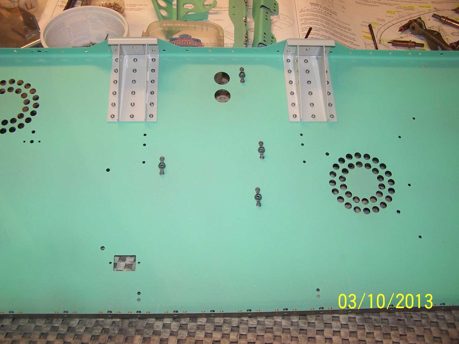
And finally, the com supports are also installed onto the base.

The underside (inside of cabin) of the panel base showing the manufactured heads of the blind rivets.


Another shot of the panel base with the cleco'd canopy ribs shown. Note that I will be postponing final riveting of the panel base to the fuselage until I receive the Viking Aircraft Engines fuel pump module. The fuel pump module is installed on the floor of the fuselage just below the panel base. Installation of the fuel pump module along with the fuel pressure and fuel flow transducers will be simplified by easier access to that area. The panel base and the upper forward fuselage skin install will have to wait until I am further along with the fuel system.

In the meantime, I am dimpling and riveting nutplates to the panel attach strips.

No comments:
Post a Comment